
No products in the cart.
Return To Shop


Preventing surgical display latency issues while adding AI overlays
Assess a surgical display system as a complete clinical workflow, treating latency as a performance criterion rather than merely a monitor setting. AI overlays can coexist with live images when the system accounts for both image analysis and display presentation. The priority is a clear, dependable image suited to the clinical task.
Start by defining what an overlay should communicate, who will use it, and how it will appear alongside the operative image. Clinicians must be able to distinguish the camera view from generated annotations. Decide on workflow, display layout, and signal-chain design together before introducing a new configuration.
The sections below explain why timing variation matters, how image processing and refresh behavior affect response, and how latency fits into essential-performance planning. They also describe how system-level measurements and documented criteria help clinical and technical teams assess changes consistently. This framework supports a careful review of overlay integration, visual usability, and system performance.
Key Takeaways
- Assess latency across the complete camera-to-display path; processing and buffering stages can contribute to variation even when direct-link transfer is brief.
- Keep video formats native where possible and limit unnecessary scaling, deinterlacing, and signal conversions when integrating overlays.
- Evaluate frame intervals alongside refresh rate: buffering a frame can add delay, so a higher frame rate alone does not ensure responsive display behavior.
- Define latency as part of essential-performance planning, then assess the display system against that requirement under expected operating conditions.
Why does latency jitter matter?
Latency jitter is variation in the delay between a camera action and its appearance on screen. Inconsistent timing can make visual feedback less predictable during an operation.
Latency Across the Camera-to-Display Pipeline
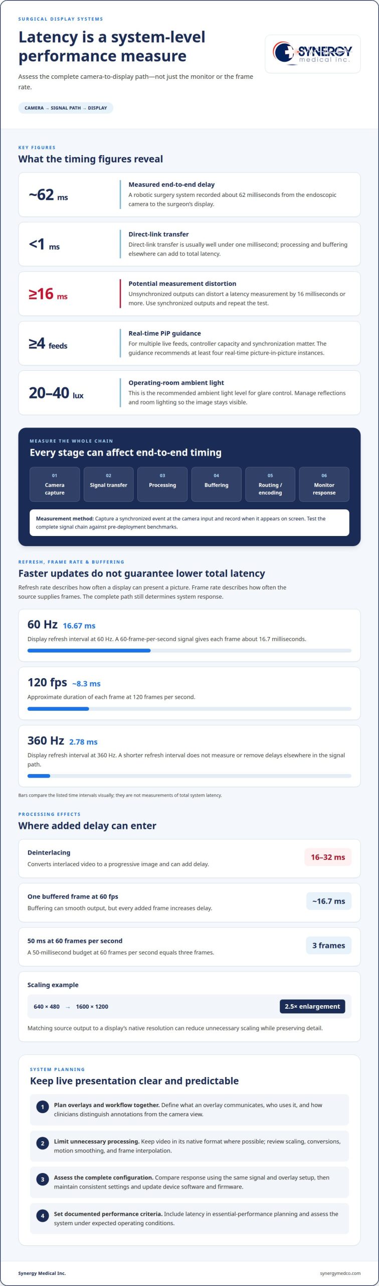
Camera capture, signal transfer, processing, buffering, and monitor response each contribute to end-to-end latency. A measured robotic surgery system recorded about 62 milliseconds from endoscopic camera to surgeon’s display, while direct-link transfer is usually well under one millisecond. To measure the full path, capture a synchronized event at the camera input and its appearance on the screen. Unsynchronized outputs can distort measurements by 16 milliseconds or more, so use synchronized outputs and repeat the test.
Video Wall and Picture-in-Picture Delays
Video wall controllers combine and route sources, while picture-in-picture (PiP) displays multiple feeds on one screen. Every processing stage can add delay, and screens in a wall may respond at different times. A controller that takes a few seconds to register an input can disrupt use. With multiple live feeds, controller capacity and synchronization matter; the guidance recommends at least four real-time PiP instances.
Touchscreen monitor settings can also affect displayed processing. Review enabled image enhancements and scaling, then compare the response with those settings adjusted. For glare control, the recommended operating-room ambient light level is 20-40 lux. Control reflections and room lighting so the image remains visible without prompting staff to change monitor settings during the operation.
Latency Effects on Surgical Motor Control
Motor control depends on the screen matching the surgeon’s actions. If instrument movement appears late or varies between frames, the surgeon may act on an earlier image, making precise movements harder to coordinate. Test latency across the complete signal chain against pre-deployment benchmarks. Then maintain consistent settings and update device software and firmware, including the monitor, encoder, and control system.
Can you add AI overlays without increasing latency?
AI overlays can be integrated while limiting added delay if the system separates time-critical display tasks from detailed image analysis. Preventing surgical display latency issues starts with planning how overlay data is prepared and presented alongside the live camera image.
Video Processing and Signal-Conversion Delays
Signal conversion, routing, decoding, and buffering add processing stages before video reaches the display. Keep signals in their native format where possible to avoid unnecessary conversions. Hardware-based blending can combine the camera image and overlay, while pre-analysis prepares overlay data before presentation. A dedicated audiovisual network can separate video traffic from unrelated activity. These choices help preserve live display response while supporting image analysis.
Display Processing Features
Display features modify incoming images before they appear, and some add computation or buffering. Disable motion smoothing or frame interpolation when unnecessary, and use a low-lag mode if available. Compare response with the same signal and overlay configuration. This helps determine whether an enhancement changes timing or image presentation, rather than assuming the overlay caused the delay.
Scaling and Signal-Processing Latency
Scaling adjusts image dimensions to match a display’s native resolution. Deinterlacing converts interlaced video into a progressive image and can add 16-32 milliseconds of delay. For example, scaling a 640×480 signal to a 1600×1200 display requires 2.5× enlargement. Matching source output to native resolution can reduce unnecessary scaling while preserving detail.
Overlay analysis can focus on relevant regions, such as the surgical site or active instruments, while background areas receive less processing. Separating rapid display tasks from deeper analysis supports timely presentation without applying identical analysis to every part of each frame. For systems combining multiple sources, video integration solutions help address signal flow and display routing.
Does a higher frame rate reduce latency?
A higher frame rate shortens the interval between captured frames, but it does not eliminate delays elsewhere in the video path. Responsiveness also depends on frame timing, buffering, encoding, and display refresh.
Refresh Rates and Frame Intervals
Refresh rate sets how often a display can present a new picture, while frame rate determines how often the source supplies frames. At 60 Hz, the display refreshes every 16.67 milliseconds; at 360 Hz, the interval is 2.78 milliseconds. At 120 frames per second, each frame lasts about 8.3 milliseconds. These intervals help explain why faster updates can make motion appear more responsive, but they don’t measure total system latency.
Frame Rate Tradeoffs
Higher frame rates require the camera, interface, network, and display hardware to handle more frames consistently. A 60-frame-per-second video signal gives each frame about 16.7 milliseconds; buffering one frame adds roughly that much delay. A 50-millisecond budget at 60 frames per second equals three frames. Select a rate supported across the full path, then assess response and image quality together.
Software Buffers and Video Encoding
Software frame buffers hold pictures while a system processes or synchronizes them. This queue can smooth output, but every added frame increases delay. Video encoding and decoding also take processing time, depending on the format and hardware. Assess the complete path, including encoder, network, decoder, and monitor, rather than judging latency by a single interface or frame-rate setting.
Compression and Frame Buffering
SDVoE systems carry video over Ethernet, so network transport and processing remain part of the timing path. Intra-frame compression encodes each picture independently and can affect processing demand and image detail. Monitor overdrive adjusts pixel transitions, while frame buffering stores whole frames. These are different functions. Check whether either adds processing or queues frames in the actual display chain.
Latency as a medical-device essential-performance requirement
Display latency belongs in essential-performance planning because surgical teams depend on timely visual feedback. Under IEC 60601, manufacturers define their medical device’s essential performance. Latency therefore matters when delayed output could affect the device’s intended function.
There isn’t one acceptable latency value for every procedure. A typical glass-to-glass target is no more than 50 milliseconds, with a worst-case target of no more than 80 milliseconds. The appropriate performance criteria depend on the task, the displayed information, and the complete video path. Defining those criteria begins with identifying how clinicians use the live image.
Added latency and total latency describe different measurements. A study of laparoscopic surgeons and trainees found significant performance and user-experience deterioration at 105 milliseconds of added latency. Separate research found degradation at around 130 to 160 milliseconds of total latency. These figures shouldn’t be treated as interchangeable limits. The measurement boundary must be clear before a result can inform system requirements.
Set the measurement boundary from camera capture to display output, then record typical and worst-case results, including frame-to-frame variation. A monitor-only test can miss delays caused by processing, encoding, routing, or buffering elsewhere. Document the signal configuration and operating conditions so later measurements can be compared consistently.
Testing should reflect intended use and the device’s stated essential-performance criteria. Repeat measurements after changing a camera, video processor, network, or monitor, as each may alter visual feedback. For engineers and clinical teams, including latency in performance evaluation, rather than treating it as a display-selection issue alone, provides a consistent basis for reviewing system changes.
Synergy Medical
Synergy Medical Inc. helps healthcare teams consider display equipment as part of a surgical video system. When reviewing latency requirements, match monitor selection to the signal format, intended use, and performance criteria established for the complete system. The display is one part of the signal path, alongside cameras, processing, and connections.
Synergy Medical Inc. offers Surgical Monitors, Radiology Monitors, Mammography monitors, and Exam Lights. These categories address different clinical display and lighting needs and are not interchangeable. For a surgical visualization project, discuss the display requirements and how the monitor fits the planned setup.
Contact Synergy Medical Inc. to discuss your display requirements.
Set the next display decision around the workflow
Before introducing an AI overlay or changing a display configuration, decide who owns the system’s performance criteria and how changes will be evaluated. Record the intended workflow, selected video sources, and overlay behavior in a shared project plan. This gives clinical, engineering, and procurement teams a common basis for discussing the setup.
A useful next step in preventing surgical display latency issues is to discuss the planned configuration alongside its clinical use. This keeps equipment decisions tied to how the system will be used, rather than treating the screen as an isolated component. Synergy Medical offers Surgical Monitors, Radiology Monitors, and Mammography monitors for healthcare environments.
A clear plan gives your team a practical starting point for evaluating the display system as it evolves.
Frequently Asked Questions
Does a one-second lag always mean there is a network problem?
No. A one-second lag can result from buffering, video processing, signal conversion, or a network issue. Isolate the source by comparing the camera’s output with the display response, then compare points before and after network equipment. If delay is present before network transmission, focus on the camera or processing path. If it appears after a network hop, examine that segment and its traffic conditions.
Is using multiview (PIP/PBP) inherently slower?
No. Picture-in-picture and picture-by-picture are not inherently slower; added delay depends on how the display or controller combines and processes sources. For example, a system may route one feed directly while scaling another for a smaller window. Compare each source on its own with the multiview layout enabled, keeping resolution and display settings consistent. This reveals whether composition, scaling, or routing changes response.
Should surgical video be compressed?
Compression can reduce the data rate needed to transmit video, but encoding and decoding add processing steps. The right choice depends on the available signal path, image-detail needs, and measured system response. Intra-frame compression processes each picture independently, unlike methods that rely on multiple frames. Evaluate image quality and timing together using representative motion, such as instrument movement, not just a static test pattern.
What adds the most latency in a camera system?
No single component always adds the most delay. The largest contribution depends on the camera, processing hardware, signal conversions, buffering, and display behavior in that configuration. A camera sensor’s readout, image scaling, or deinterlacing may matter in one system; queued frames may dominate another. Measure points along the complete path under the same operating mode to identify the main contributor.
What happens if surgical displays lag by just 1 second?
A one-second lag means the displayed image shows an earlier moment, not the instrument’s current position. That gap can disrupt hand-eye coordination because actions rely on outdated visual feedback. The practical effect depends on the task and how much the operator relies on live video. Treat a full-second delay as a system-performance concern and assess it before using that configuration for time-sensitive surgical visualization.
What is glass-to-glass latency?
Glass-to-glass latency is the elapsed time from an event captured by the camera sensor to that same event appearing on the display. A visible instrument movement, for example, provides a reference event at the camera and a matching event on screen. The measurement includes capture, transport, processing, and display, so it describes the full imaging path rather than one device’s response.
About author
